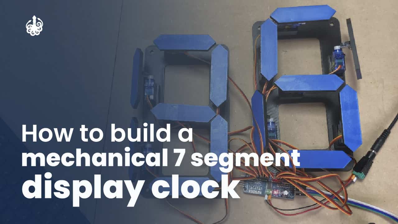
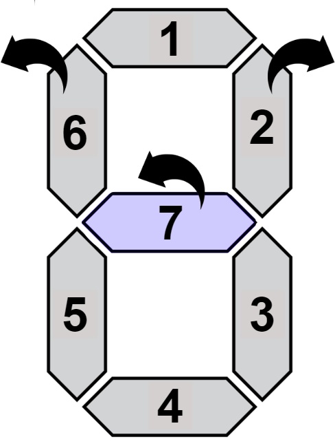
This mechanical clock is based on the 7-segment LED display, unlike this, in which each LED turns on and off with a voltage level, this mechanical clock changes the position of each segment to hide or show the segment. The horizontal position shows the segment face, while the vertical position shows only a thin border (hidden).
Each servo can change the segment’s position, so it must be calibrated to move in the desired direction and distance. In some cases, such as the middle segment ( number 7), it is necessary to move the side segments to allow movement.
This means that to create our clock we need 7 servos per digit, that is 28 in total. This is too many servos to control and that is the reason why we use a PWM expander, the PCA9685 from Adafruit, which allows us to control up to 16 servos with only 2 pins (I2C). 16 servos with only 2 pins (I2C). As for the Time measuring, we decided to use the internal RTC of the esp32 and the internet to keep the time up to date and reduce the number of components.
Supplies for the 7 segment clock
Here you can find everything you need to build your own Mechanical 7 Segment Display Clock.

- ESP32 DevKit – Buy Here
- 2 x PCA9685 16Ch Servo Drivers – Buy Here
- 28 x Micro Servos – Buy Here
- Black Spray Paint – Buy Here
- 5V 3A Wall adapater – Buy Here
- Jumper Wire Female to Female – Buy Here
- 30AWG Wire – Buy Here
- 3mm MDF (Or other options to set the digits)
Step 1: 3D Print the Plastic Components
There are two groups of parts for 3D printing:
- Base supports
- Segments


We printed the parts all in the same color (blue), but to differentiate the ON and OFF state of the segments, we decided to paint everything in black except the surface of the segment that will be shown.
The Base supports we created to make it easy to install the servos and also to attach them to the MDF board since we included holes for screws and the frame already has the spacing between the digits of the clock.
The files for printing, the base, and segments, can be downloaded from the repository in the 3D Printing folder.
Download the 3D printing files here – DIY Mechanical 7 Segment Clock
The printing configuration that we recommend is:


To compile the code you need to install the Adafruit PCA9685 library:
- Adafruit_PWMServoDriver – https://github.com/adafruit/Adafruit-PWM-Servo-Driver-Library
you can download the zip from Git Hub or use Arduino Library Manager.
Code Explanation
The ESP32 is in charge of moving every servo motor in its right position to represent a number of the current time clock. The time is tracked using internal RTC and synchronized occasionally using NTP server. Every time 1 minute passes, the servos position is updated. The current time is split in digits to assign to every group of servos.
Every digit is a Class that controls the 7 segments/servos. Inside the “SevenSegment” library we handle all the motor movement. The library takes care of setting the position of every motor according to a desired number representation. It’s in charge of moving the side segment to update the mid-segment as well and provide a good abstraction to support other applications different from a Clock.
Internally this library is called Adafruit PCA9685.
The user only needs to configure a couple of things like:
- Wifi Network Credentials:

- NTP Server and TimeZone

For TimeZone strings check this CSV
Step 5: Assemble & Calibrating of Segment’s position
To assemble the segments to the servo you need to configure a position as a reference. We need to put all the segments ON, show 8 in all the digits 88 88.
For that, we select the CalibrateServos function and comment InitClock .


After the previous instructions, you should have a Clock like this: